
Uploader 1.0

Introduction
Programming an i-Cybie cartridge is not a hard task, but all the solutions I found on the Internet needed at least two of the following items:
- A modified dog (with serial port communication). Details at
http://www.aibohack.com/icybie/sic_rs232.htm - A working cartridge (this is a bit obvious. The one that comes with the dog has just an empty pcb in it!).
- Some way to connect the cartridge to a PC. It can be done through the dog itself (item 1) or using a downloader.
All the above may be quite straightforward to someone in the USA or Europe (I suppose...). But in Brazil, for instance, electronic stuff is overtaxed and a bit hard to import. I-Cybies were sold by a local toy manufacturer (Estrela) but the
only thing they brought here was the dog original box, with it's charger, remote control and NiCd battery.
So, when I decided to change the personality of my dog, I got to a dead end. The best solution seemed to be 'SIC'ing it, but it would require a cartridge with a special program (CROMINST). Great: To be able to write something to the cartridge I needed a cartridge with something already written. A chicken-and-egg dilemma.
And there is another reason, a very private one, I must confess: I WANTED TO DO IT. lol. It was something I didn't know how to do, and things that I don't know makes me nervous.
Then, I decided to build my own cartridge programmer based on the (too few) technical information available (links on the bottom of the page) and on component data sheets.
And here it is! The I-Cybie uploader.
It may be a bit hard to believe, but it works!
1) The Cartridge
The I-Cybie cartridge - I mean, a working one - has two 1Mbit SST39vf010
 flash memory chips on it. That makes 256Kbytes - 2Mbits, not 2Mbytes as sometimes I read. As any memory chip, the pins are the address bus (17 bits), the data bus(8), 3 control signals (write enable, output enable and chip select) and power. Reading it is done just like any memory chip, but writing to it and erasing it requires a special protocol- just like any flash chip. It's all documented in the data sheet. You better take a look if you want to go deeper.
The images below shows both sides of the cartridge pcb with labeled pins. Those images are from Danh Trinh's site, http://www.imaginerobots.com.


The SST chips are quite cheap and if you have good soldering skills, a magnifying glass and a steady hand you can populate the cartridge yourself. There are some SMD soldering kits in the marked to help you, if you need. The radio and TV repairs guys
that you probably know may also have the necessary skills and equipment to do it, in case you are afraid...
Once a working cartridge is available, the next step is building the programmer.
that you probably know may also have the necessary skills and equipment to do it, in case you are afraid...
Once a working cartridge is available, the next step is building the programmer.
Yes, it's a lot easier and cheaper to use a SIC and yes, I'm reinventing the wheel, but there are some scenarios that makes this uploader a good option:
- there is no way for you to get a cartridge with CROMINST;
- you don't want to drill holes in your dog and poke it's inner parts (at least, for now!);
- and you can't or just don't want to buy a downloader.
microcontroller running at 10MHz, a MAX232CPE, three buffers and some passive components. The circuit is powered by a 3V source that can be
two AA batteries. It is linked to the serial port of a PC at 57.6Kbps.

Don't worry if it's a bit hard to see the details and, anyway, they might be outdated.
There is a zip file with detailed (and updated) information about the entire project at the end of the page.
The PCB is a single face board with dimensions 90x70mm:

One part must be home-made: the cartridge connector. If you take a closer look and pay attention, you'll notice that the pads displacement are the same as a PCI card. So... all you need to do is getting a PCI slot connector and cut it at the same size of the cartridge (2 rows of 20 pins). After that, solder a flat cable to the pins, like this:

RS232 cable: Another part you may need to wire yourself. The connector on the pcb is the same one found on PC mainboards for a DB9 serial
port. So, the pin layout is the same as any PC serial port. All you'll need is to get a null modem cable or make one like this:

3)Software
There are two different codes, one inside the microcontroller and one running at the PC. The PIC code was written in C using SouceBoost and
the PC code was written in MS Visual Basic 6.0. Full souce code, binaries and installation packages are available at the botton of the page.
3a. PIC Code: The PIC code receives commands from the PC host and executes them. You don't need to know the correct sintaxes of the commands (except for the debug mode ones), since the software running on the PC manages everything for
you. Available commands are:
- Cartridge Erase: Erases both flash chips.
- Cartridge Read. Reads the flash chips and send the data to the PC. Estimated time: 50 seconds.
- Cartridge Write. Writes the flash chips with data from the PC. Estimated time: 8 minutes.
- Firmware version. Sends this information to the PC. Also used to check communication.
- Debug Mode: This is a special command useful to detect hardware bugs. To use this, it's necessary to use another communication program, like Hyperterminal.

The button commands are (from left to right):
- Load personality file: Loads H and L bin files from disk.
- Save personality file: Saves the data read from the cartridge to disk files.
- Erase Cartridge.
- Load cartridge data.
- Upload to cartridge. This is the command to actually save something to the cartridge. It erases the cartridge if you forget to do it yourself.
- Verify Cartridge. Compares the data read from the cartridge with the one in the PC buffer.
- Communication check.
- Configuration - Serial Port. To set the serial port used by the program. Must be set before the first use.
- Configuration - Verify after upload. Check this to make an automatic verify after programming the cartridge.
Freeware disclaimer: The author, Luiz Cressoni Filho, of this freeware accepts no responsibility for damages resulting from the use of this
product and makes no warranty or representation, either express or implied, including but not limited to, any implied warranty of merchantability or fitness for a particular purpose. This software is provided "AS IS", and you, its user, assume all risks when using it.
Here are the files you will need to build and use your uploader:
- Hardware: Squematic pcb layout and part list. (updated 16/02/2005)
- Software bins: PIC binary and PC instalation package.

- Software source codes. PC Visual Basic and PIC SourceBoost projects.
Links:
- http://www.i-cybie.com -
Guess what!
- http://www.i-cybie.net -
Here you'll find a very good forum about cybie and other robot pets. - http://www.buy-cybie.com -
Everything you need to buy for your dog
can be found here. It is the best - if not the only -
place for Cybie parts and accessories.
- http://www.aibohack.com/icybie/index.html - Some good informations, pictures, videos, technical data, personalities, editing software. Must see!
- http://www.imaginerobots.com.- Danh Trinh's site. Technical informations about Cybie like charging charts, dessication pics, pcbs and lots more.
6) DebugMode
If something doesn't work, try to connect to the uploader using a terminal program like Hyperterminal. Connect to the serial port using the configurations below:
- Bits per second: 57600
- Data bits: 8
- Parity: none
- Stop bits: 1
- Flow control: none
I-Cybie Uploader 1.0
Absolutely NO warraties of any kind.
If it doesn't, take a closer look at the serial communication block of the circuit and see if the PIC is actually running. If it does, the available commands are (all single key press):
- 'D' - enters debug mode
- 'W' - activates the write enable line. It will remain low until you press a key.
- 'O' - (letter O) activates the output enable line. It will remain low until you press a key.
- '0' - (number zero) activates the chip select 0 line. It will remain low until you press a key.
- '1' - activates the chip select 1 line. It will remain low until you press a key.
- 'A' - activates address lines from A0 to A16, one by one after each key press.
- 'C' - activates the latch clock lines (all 3 lines). They will remain high until you press a key.
- 'X' - Exits debug mode.
- Cartridge:
- 2 SST39VF010-70-4C-WH
- 1Mbit flash memory, TSOP package - 2 0.1uF bypass capacitor (SMD) - you can get these in any old computer hardware board
- Programmer:
| Quantity | Reference | Value |
| Resistors | ||
| 2 | R1,R2 | 120R |
| 5 | R3-R7 | 10K |
| Capacitors | ||
| 5 | C1,C5-C8 | 1uF 16V |
| 2 | C2,C3 | 22pF ceramic |
| 1 | C4 | 0.1uF ceramic |
| Integrated Circuits | ||
| 3 | U1-U3 | 40174 |
| 1 | U4 | PIC16F876A |
| 1 | IC1 | MAX232CPE |
| Diodes | ||
| 1 | D1 | Green LED |
| 1 | D2 | Red LED |
| Miscellaneous | ||
| 1 | CC1 | Cybie Cartridge slot connector (see text) |
| 1 | X1 | 10MHz crystal |
| 1 | RS232 connector (see text) | |
8) Pictures (took with a Palm Zire 71. Send me a better camera if you don't like these shots):

Fully assembled PCB. Note the RS232 flat cable at bottom left of the PCB. I took this cable from an old PC mainboard.
The black wire over the resistor pack is there due to a PCB mistake,already corrected on the downloadable layout.
The PCB corners were cut to fit inside the box.
The box: I picked up and old 3 1/2" floppy disk box and drilled some holes on it.
From left to right, 2 LEDs, the cartridge slot and the DB9 connector.

This is how the connections look like .
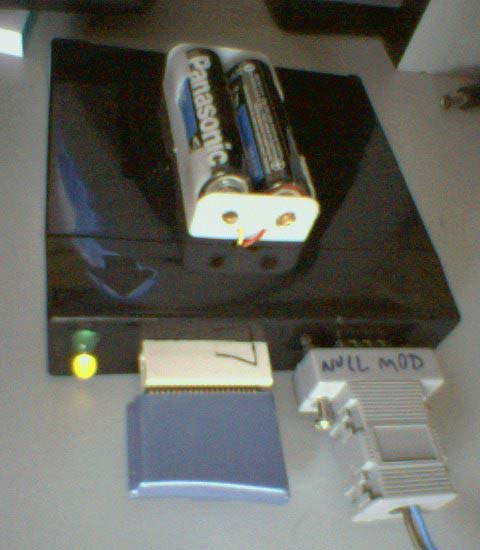
Uploder working. The yellow LED indicates it is saving something (in this case, it is uploading data to the cartridge).
Green, when lit, indicates read operations.
Hi! Did you like the project? If so, why don't you click on some adds to help me improve it?
ResponderExcluirHello!
ResponderExcluirThanks al lot for your great work!
I have a cybie with a cartridege with only one chip ( SST39VF200A 70-4C) on the PCB. Do you think I can program this cartridge with the personalities on the AIBO/Cybie Hack page? Is your programmer able to program this cartridge or need the HW or SW a modification? My Cybie is a model after 2005 with a walk up charger.
Greetings from Salzburg (AUSTRIA)!
Alexander Wagner
Greetings from Brazil, Alexander. Unfortunately, the software must be modified to save on that chip. The SW as it is now expects two memory chips and will return an error code if it finds only one.
ResponderExcluirHey Luiz - you still around? I'd love to get this project going again.... Mick (UK)
ResponderExcluirHey Luiz, I have two 2001 I-Cybies and one 2005 I-Cybie. I've been planning on making working cartridges someday, I currently have two cartridges with unpopulated pcbs and I'd like to build an uploader like yours some day once I have all the tools and parts needed. Wondering, do you still have the files that are linked here from the neocortex website? Looking forward to preserving I-Cybie since they're such great sophisticated robo pups...
ResponderExcluirHope to hear back from you!
(Mike - aka SkylarZYX, USA)
Try this. I made a new version using an Arduino 2560. https://www.pilothobbies.com/i-cybie-cartridge-programmer-using-arduino-mega-2560/
ExcluirWow! I've had prior experience with arduinos before so this might be even more of a great opportunity to finally make a programmer. Just have to get the tools needed to pull this off. Thank you SO much for making this !
ExcluirParabéns pela iniciativa, mesmo tendo sido a muito tempo atrás ela continua válida para muitos.
ResponderExcluiros links abaixo podem ser refeitos?!
http://www.neocortex.com.br/images/cyb_up_sq.pdf
http://www.neocortex.com.br/images/cyb_up_bin.zip
http://www.neocortex.com.br/images/cyb_up_src.zip